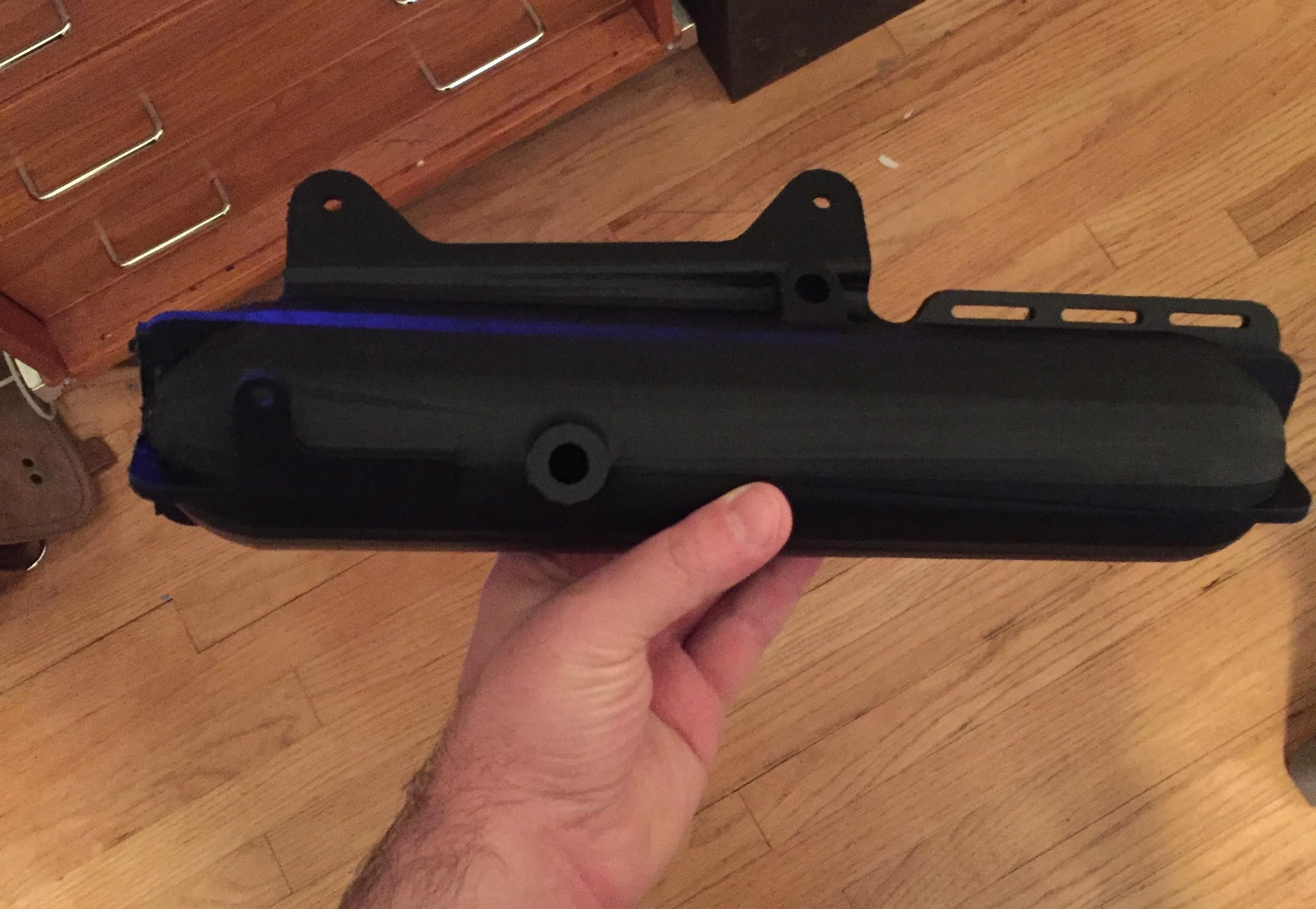
One of our research questions for the Blacktip platform was “Can ballast tanks be 3D printed?”. While we are still exploring this question, we believe the answer is “yes, under the right conditions”. The picture below shows Blacktips current, 3D printed, ballast tank.
Blacktip’s ballast control system runs off of a pressurized gas source. It is an open ported design where there is an always-open “drain” at the base of the tanks. When the air pressure inside the top of the tank is greater than the water pressure outside the tank, the pressure differential causes the tank to drain until the internal and external pressures equalize. Should there still be a positive pressure differential in an already empty tank, the air to leaks out the drain until the internal and external pressures are equalized. Similarly, if there is a negative pressure differential water leaks back into the tank compressing the contained air, until the pressures are equalized.
All the components for one half of the ballast system can be seen in the cutaway figure below. The tubing between the various components is not shown to simply the figure, but PEX pressure rated tubing is run between the visible connectors.
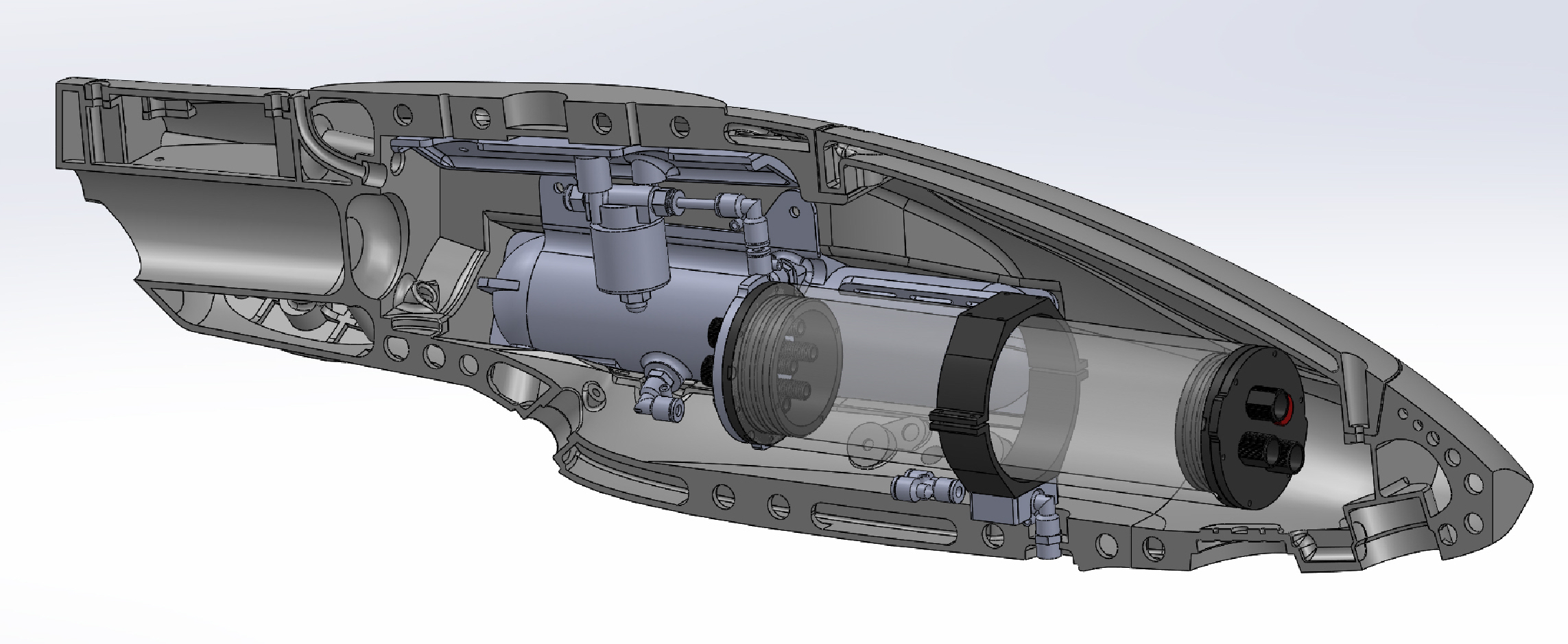
While there are two ballast tanks, one port and one starboard, they tanks are cross-linked and act as a single tank. There are two valves on the system, one connecting to the curved tube, visible as a feature of the hull here, acts as a vent valve. The vent allows for the controllable outrush of air to sink fill the ballast tanks, as well as the inrush of water during an emergency re-righting operation. The other valve (not show but symmetrically placed in the cutaway’s non-visible half) gates the flow of pressurized air into the top of the ballast tanks. Both tanks share the single external drain, visible in the cutaway above directly under the main electronics support.
Keel weights are added to inter hull chamber visible along the base of the hull. The weights set the center of mass such that the hull will want to self right into an alignment where the ballast control is functional. If the hull is for some reason inverted, the system can attempt to recover by opening the top port valve, flooding the tanks, then re-draining the tanks after the hull has sunk to hopefully calmer waters and self righted.
3D Printed Ballast Tanks
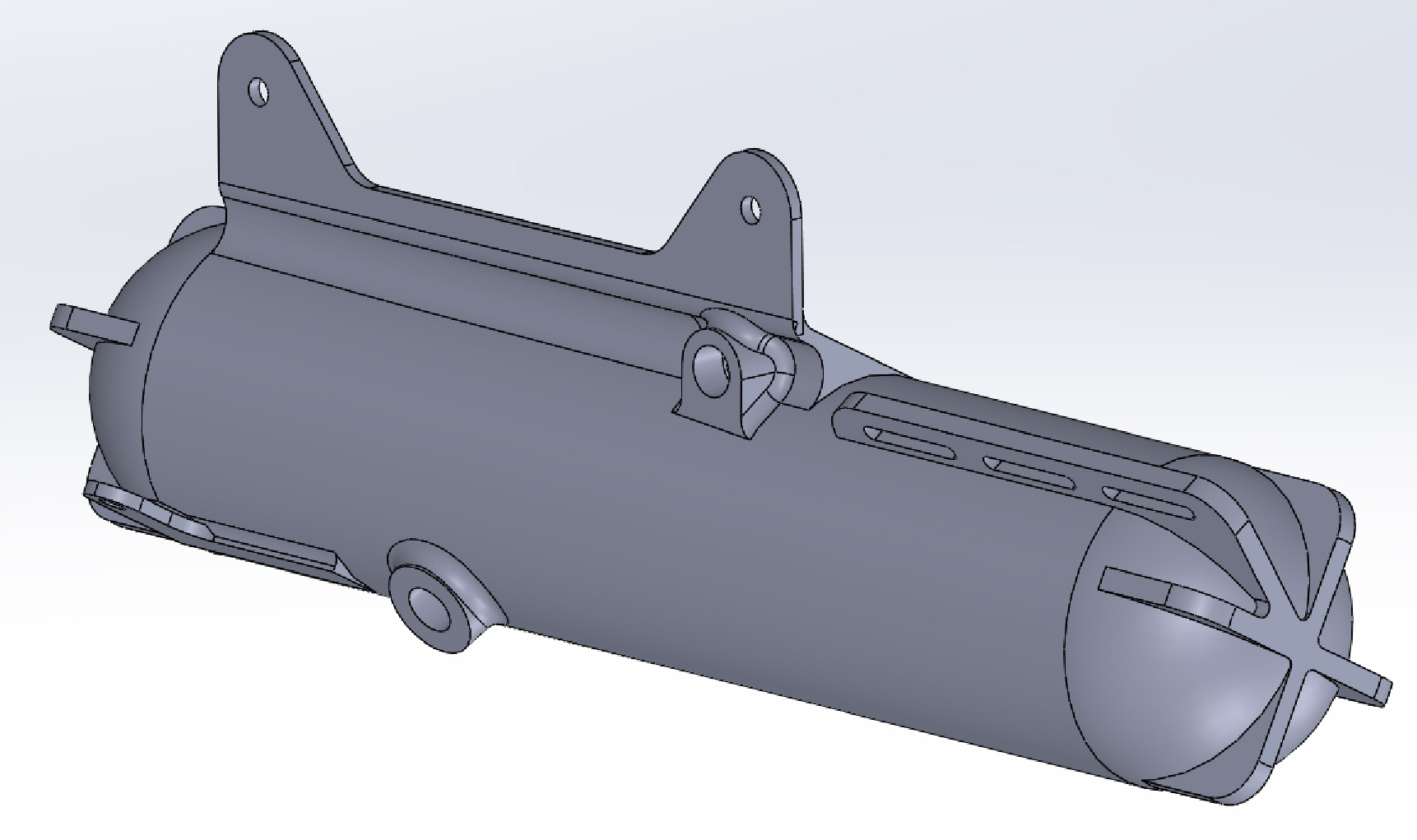
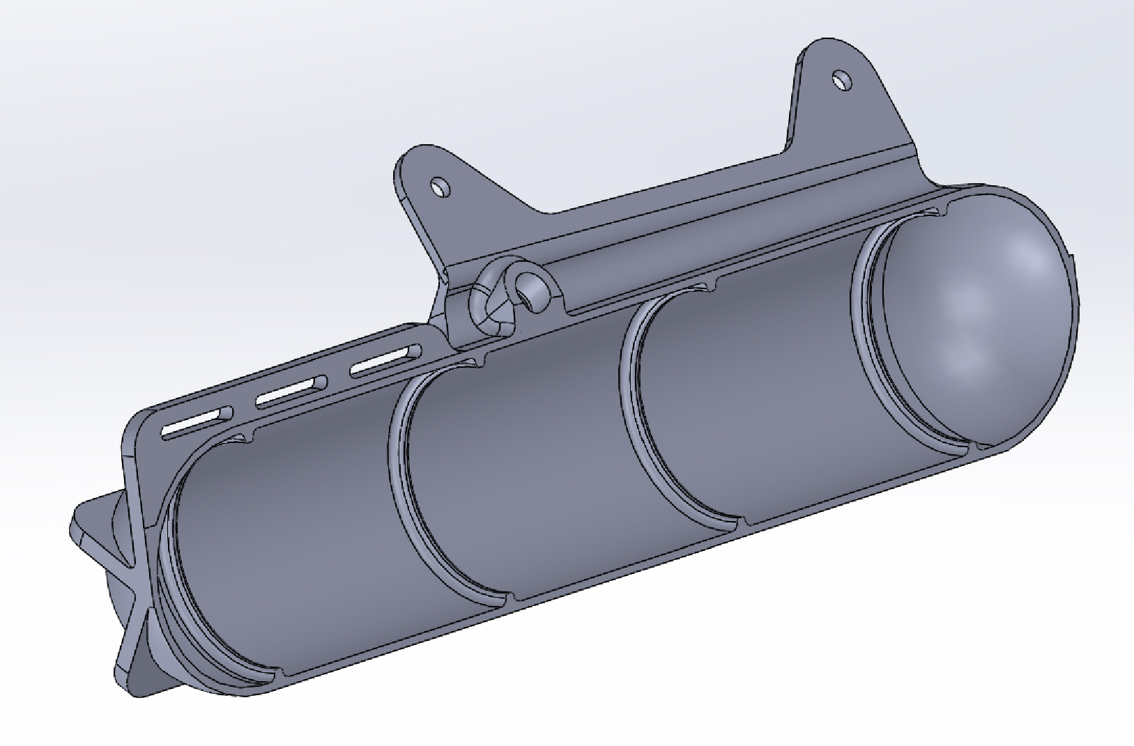
Internally the tank has a series of spars, visible in the tank cutaway below. These are both to provide additional strength for a pressure bearing part, and act as partial slosh baffling. Outside the tank there are also a series of slots meant as convention zip tie points for securing otherwise loose cabling and tubing inside the hull.
Since the pressure inside and outside the tank will always equalize – long term the tank does not have to support a pressure differential of more than a few PSI. The problems arise from short-term stresses. We have so far been unable to find a suitable way to cost effectively provide controllable pressure regulation. As a result, the current design uses a fixed 50PSI regulator, and uses short pulsed firing of the systems valves to step the internal tank pressure to its desired pressure and buoyancy in discrete steps.
It remains to be seen what the long term “air hammer” effects these short bursts have on the printed tanks, and what the expected functional life spans of the tanks will be. While two tanks does provide for a more stable hull, the main reason two relatively large tanks are used in this design, is so that if a tank fails, the remaining tank can emergency lift the hull to the surface for recovery. Full disclosure, stress testing the ballast control system is the very last thing on our research question priority queue because there is a chance failure could result in loss of the entire drone.
Working Gas Selection
The system was designed to either be run from compressed air or CO2. The initial plan was to develop using CO2, then in later versions switch to compressed air. The primary benefit of CO2 is long mission life, as one small tank holds enough potential for over a hundred worst case dive cycles. The same sized tank, using compressed air only holds a few cycles, with the number dependent on the storage pressure. The move from CO2 to compressed air is achievable with the addition of an air compressor and a semi-frequent surfacing requirement. It is a design tradeoff we were interested in making as CO2 is a greenhouse gas.
Our current thinking current thinking is that the next design wont uses a pressurized gas system at all. Since the overall mass of the system is going to remain relatively constant over even extended missions, the use of hydraulic displacement for buoyancy control should work. If it does it should be significantly cheaper and easier to engineer. For now it is a design question tabled for the next hull design.