It turns out that Syringes are rated for surprisingly high pressures. Pressures found when submerged at a depth of 80 meters. So for low cost drones intended for shallow water operations syringe based buoyancy engines provide a cheap and surprisingly effective buoyancy control.
Background
A buoyancy engine works by changing the density of part of the craft they are installed within. Typically oil is pumped hydraulically out of a sealed pressure rated chamber, and used to inflate or deflate an external bladder. As the oil is removed or added to the bladder the material inside the fixture chamber is physically changing, while its volume remains the same. This causes the chamber’s buoyancy to change. When the specific gravity of the fluid is factors in, this enables controlling the total buoyancy of the craft.
On conventional submarines ballast tanks are used to accomplish buoyancy control. Letting the tanks flood with water sink the craft. Leaking pressurized air into the ballast tanks, forces out the water, and creates areas of positive buoyancy in the submarine.
Syringe Based Pumps
A syringe based pump enables operation both as conventional ballast control where the syringe pump is essentially used in the same way as a ballast tank on a submarine, and as a buoyancy engine through pumping oil into and out of an external bladder. Since syringes with standardized tubing and interlocking systems are common, construction of all manner of fluid manipulation configurations is both inexpensive and quick to implement. For example, Leur Lock tips are already designed to interface with a number of pressure rated tubes, fittings, valves, and flow regulators.
Picture below is Rumblefish’s 30 mL syringe pump design. It is intended to be made using commonly available or 3D printable parts. The design as pictured, and tested, uses Medline 30mL Luer Lock disposable syringes (part number SYR130010).
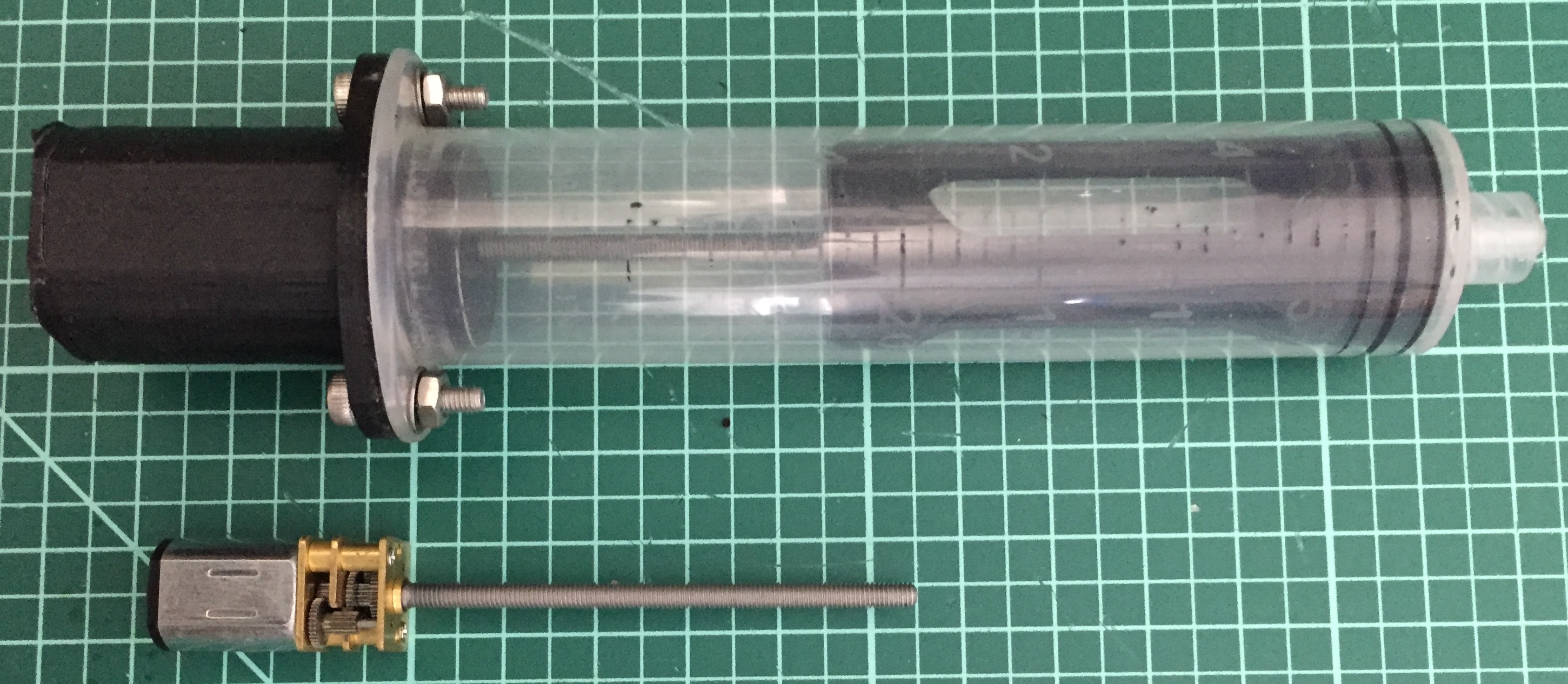
The motors used are common 55mm shaft DC brushed motors. The motor housing at the base of the syringe is meant to be air tight enabling the use of a brushed motor, even in designed where the buoyancy engine is in a flooded compartment.
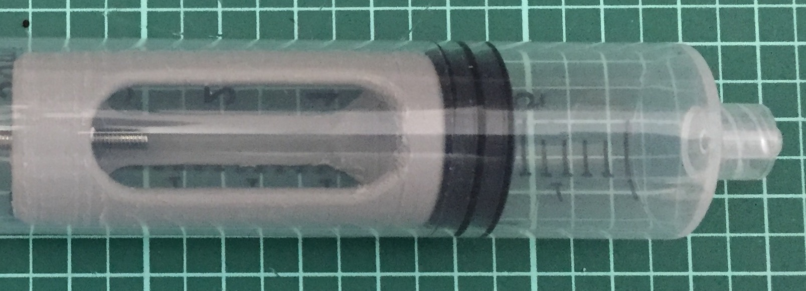
While it may look like half the volume of the syringe is wasted here – with the piston only traveling 45% of the syringe’s barrel length – this is by design. As the piston draws back from full extension the air inside the sealed end of the piston is compressed. In a design that starts out empty on the surface, the chamber is at a pressure of 14-15 PSI. Drawing back to fully extension here would increase that to nearly 30 PSI. Designs that draw back further have to deal with a steep increase in pressure as the draw is increased. The current designs draw was chosen as its worst-case pressure differential is still easily within tolerances achievable by 3D printed parts.
While difficult to see in the pictures – the piston has recesses for two 1/8th by 1/8th inch cylindrical Neodymium magnets. These magnets enable feedback on the pump control. Either magnetometers, or magnetic reed switches, can be used to detect the magnet’s position, and thus when the piston has reached the ends of its travel.