As we added components to the desired electronics in a Lanternfish we eventually hit a wall with the old electronics chamber size. Everything could be made to fit, but it was just a nightmare to assemble. The new chamber is deeper, creating a wider opening to work on the electronics, as well as creating room for an addition printed “rack” for mounting the electronics modules.
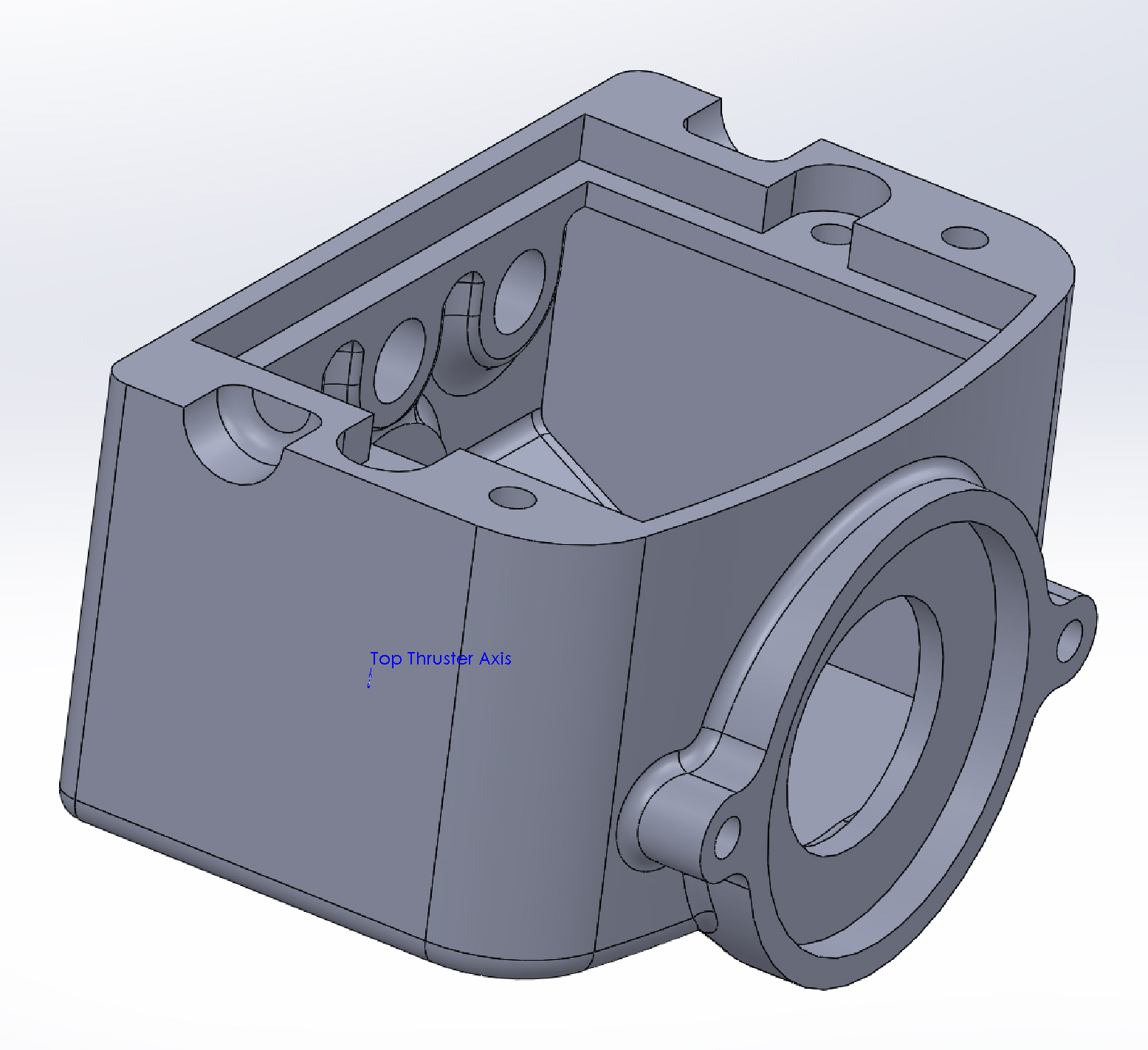
While the front of the module maintained the same profile and porthole for the camera, the back of the chamber changed significantly. The new chamber no longer uses the Cave Pearl’s pex connector trick we discussed previously. Instead all three motor connectors uses the caps you can see in the figures below. The previous design also had several capped cable passthrough points for future expansion, and all of these were removed. Short term expansion can be accommodated with the new cable cap design.
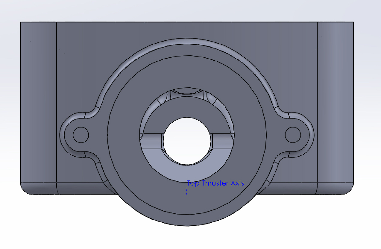
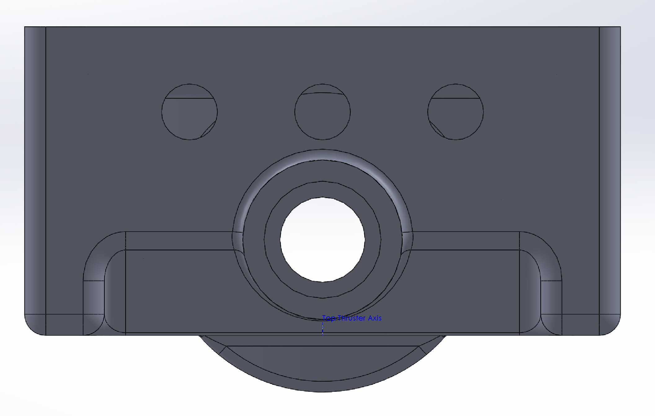
Sine just pushing out the old case design would have partially occluded the intake for the top thruster, the new design integrates a partially sloped chute to provide water flow while still increasing the depth of the chamber.
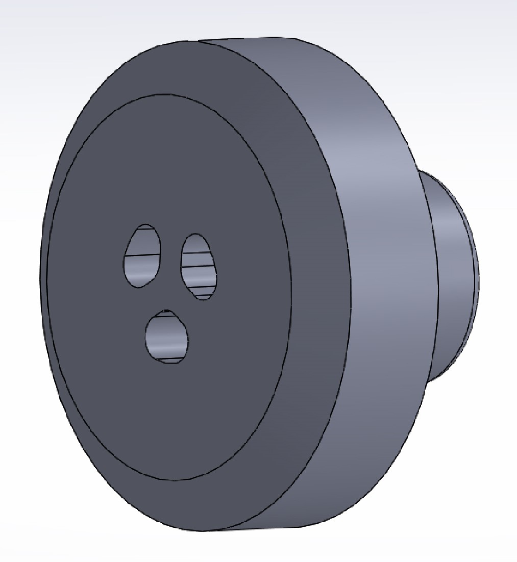
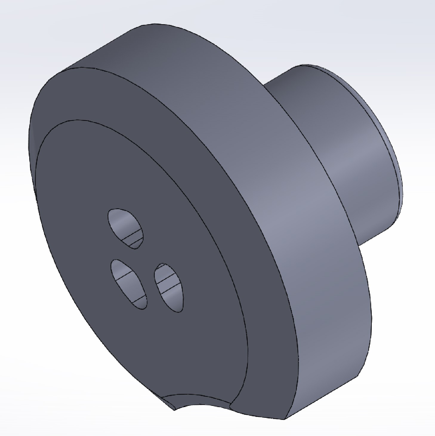
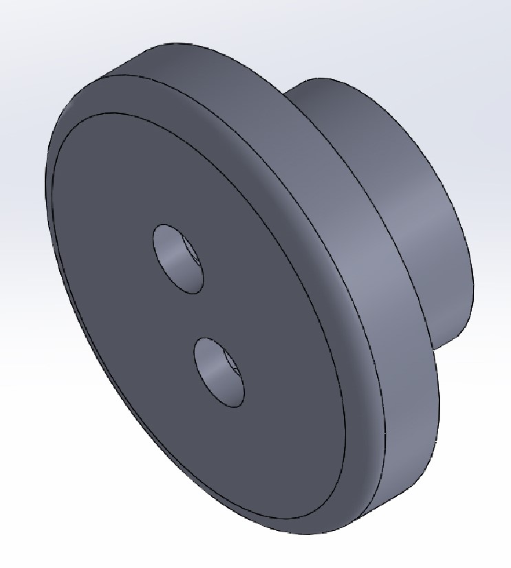
The new pass-through endcaps, seen in the picture above, each contain a small “glue cup” for potting the wires in epoxy. One of the weird problems with under water wiring is that if the cable sheath gets damaged, water can slowly travel down along the wire and into the electrical chamber. A way to combat this is to strip the insulation off a small section the wire, then pot that section in low viscosity epoxy. The “glue cups” in the end caps segregate each wire into its own “tunnel” where the stripped wires wont short together, and then the whole cap, and each tunnel, can be backfilled with epoxy.
The caps are secured to the chamber with a silicone adhesive so if needed they can be remove to swap replacements for damaged wires. Since the cap can be constructed and glued without the electronics chamber their construction can be sped up by being assembly lined in parallel.
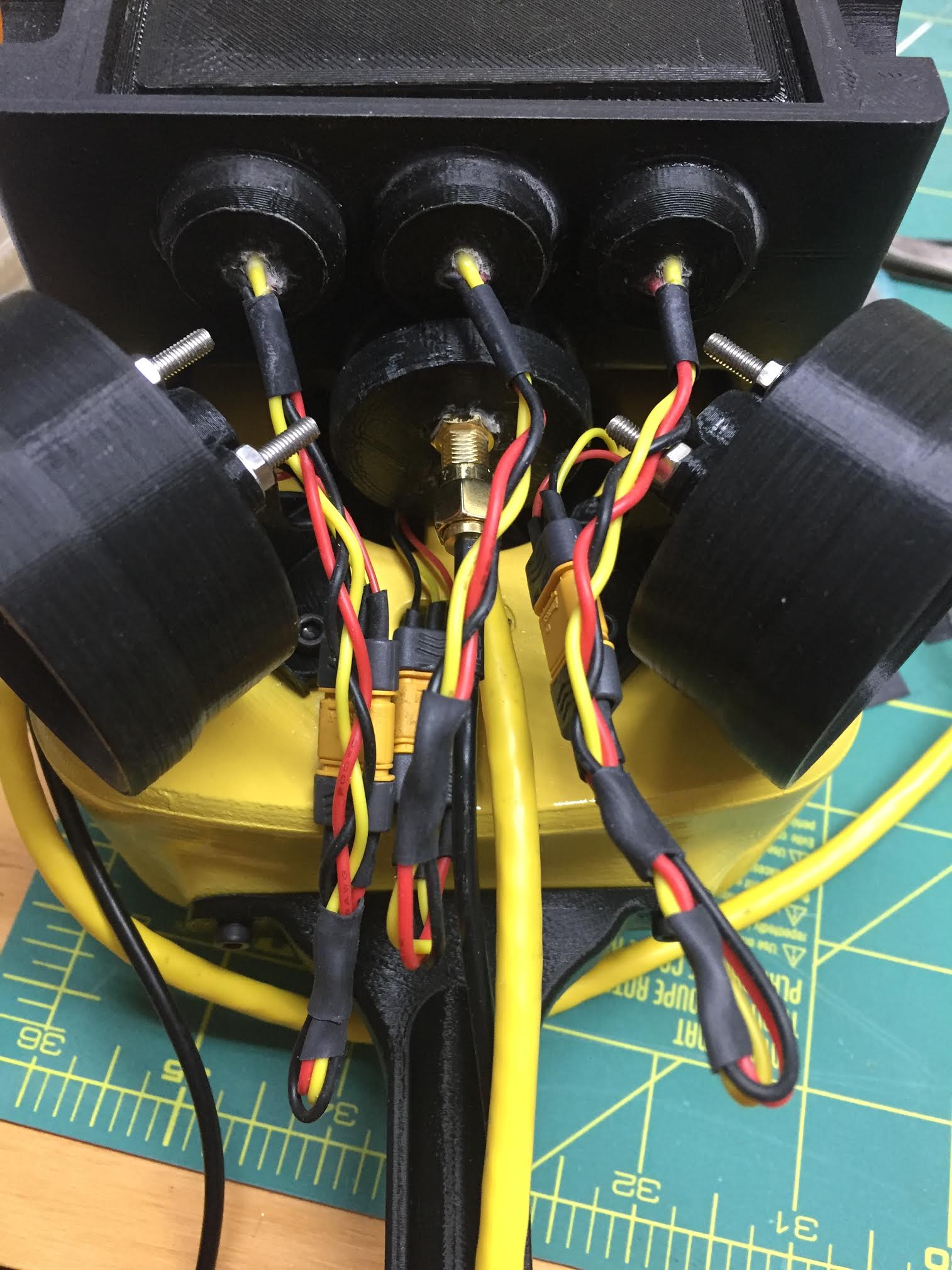
The cap wiring can be seen in the figure below, right. Ignore the super long wires – their extra length is to ease testing. We are still hunting for good, cheap, waterproof electrical connectors. The pictured Lanternfish is using MR30 plugs and silicone wire. The plugs enable swapping out motors, and the silicone wire takes a lot of abuse and has a very tiny minimum bend radius. The connectors are water proofed by applying a nylon based nail polish over their electrical connections, and along the inter connector module part line. The RF connection is just straight coax, and we are still testing how well it works for prolonged use under water.
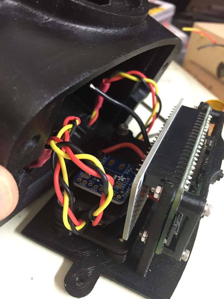
The figure above, left, shows the current electronics chamber’s contents. Several modules get soldered onto the white raspberry pi hat breakout. Then the electronics speed control and high side power monitor are on separate jigs mounting to the ceiling (the floor in this picture) of the chamber. Another jig aligns the raspberry pi camera module with the porthole. The voltage regulator, not visible in the picture, lives below the raspberry pi.