Rumblefish is spinning up a new long-term project to explore using tiny buoyancy engines in drones and ROVs. Most small to mid size drones and ROVs don’t use a buoyancy control engine at all. They use either an upward facing thruster to push them “down” into the water, or rely on hydrodynamic forces on control surfaces to push the hull “up” or “down” with forces generated by its motion through the water. While both techniques work they also both require power and or motion to remain below water. While you do find buoyancy control on underwater gliders, we are unaware of any gliders designed to go buoyancy neutral and stop and “hover” at a depth underwater mid dive.
The benefits of being able to actively control and even neutralize buoyancy for a craft seem obvious. So much so that it seems like there must be something we are missing – hence spinning up this project. A ROV or drone that dives down and goes buoyancy neutral can “listen” to its environment without the background noise of a depth control thruster periodically firing. For example, sensors on such a drone measuring properties of a water column can drift with the column taking repeated measurements while not at the same time churning up the water they are trying to measure. Similarly an autonomous drone with a task like holding a camera or a work light pointed at a diver will just need to fight drift from cross currents, and can stay on task longer with a given charge, while also having lest impact on visibility through particulate churn.
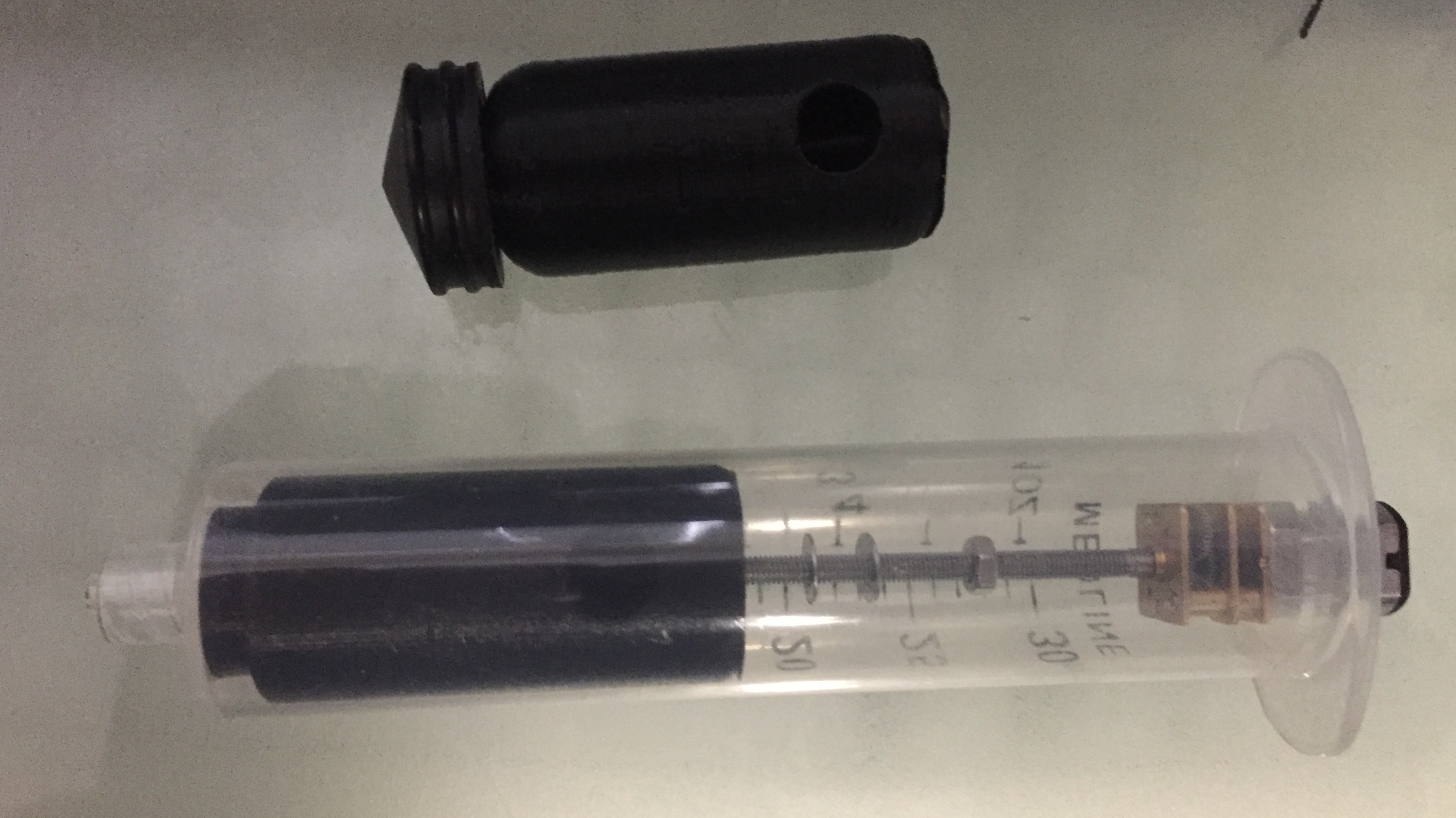
A 5cc syringe – like the one show here – can generate pressures sufficient to control buoyancy at a depth of 50 meters. So they should be perfect for a lot of the designs we want to build where the drones need to be as small as possible, affordable and fast to construct, and only have a maximum operational depth of 10-20 meters.
One experimental variable is small we can make the buoyancy engine. The range in buoyant forces the engine is capable of generating is a direct function of the volume of the fluid which it controls. Industrial drift sensors, that dive kilometers below the ocean and are the size of a car, often use buoyancy engines that only displace a few cubic centimeters of working fluid. To accomplish this they need to tune the mass and displacement volume to within a few grams of their target weight. Our engine’s size was chosen based on Fermi estimates, and available syringe sizes. It controls 14cc of working fluid. The plan is to use BBs, which weigh 0.35g, for hull trim weights. This should let our hull designs mass and trim be adjustable with enough tolerance to dial in a small buoyancy engine.
A clever trick that some of the syringe based underwater gliders use is to weight the piston. So when the piston draws back taking in water to dive, the center of mass of the piston also shifts “back”. If the syringe pump is aligned “backwards” relative to the nose of the glider this makes the nose heavier than the tail as it is diving. Similarly pushing the piston forward, expelling water to surface, makes the nose relatively lighter than the tail when surfacing. ( If you are interested in syringe based gliders both the Seaglide, and this build blog, are worth checking out).
In this first mockup pictured above we used an optionally weighted piston.
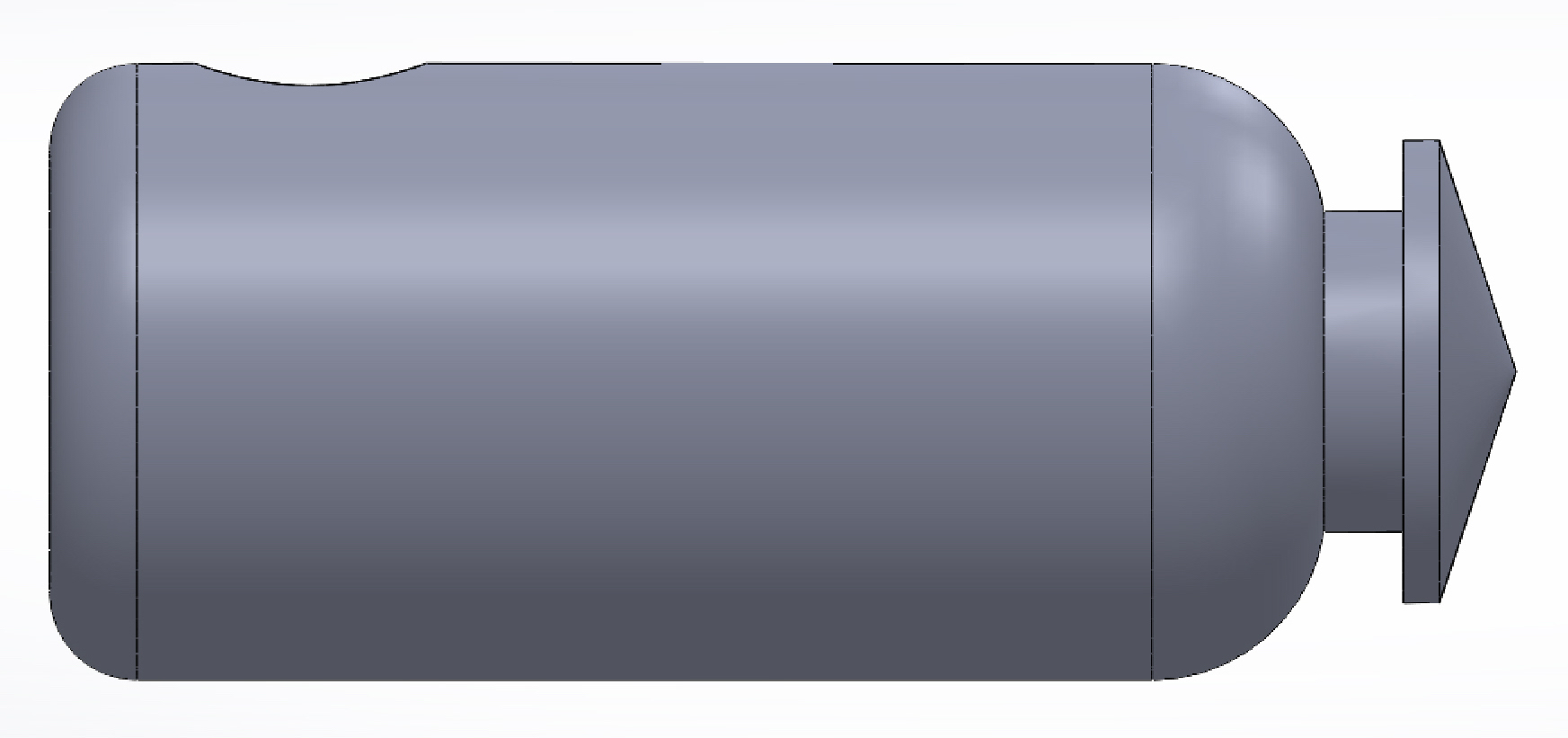
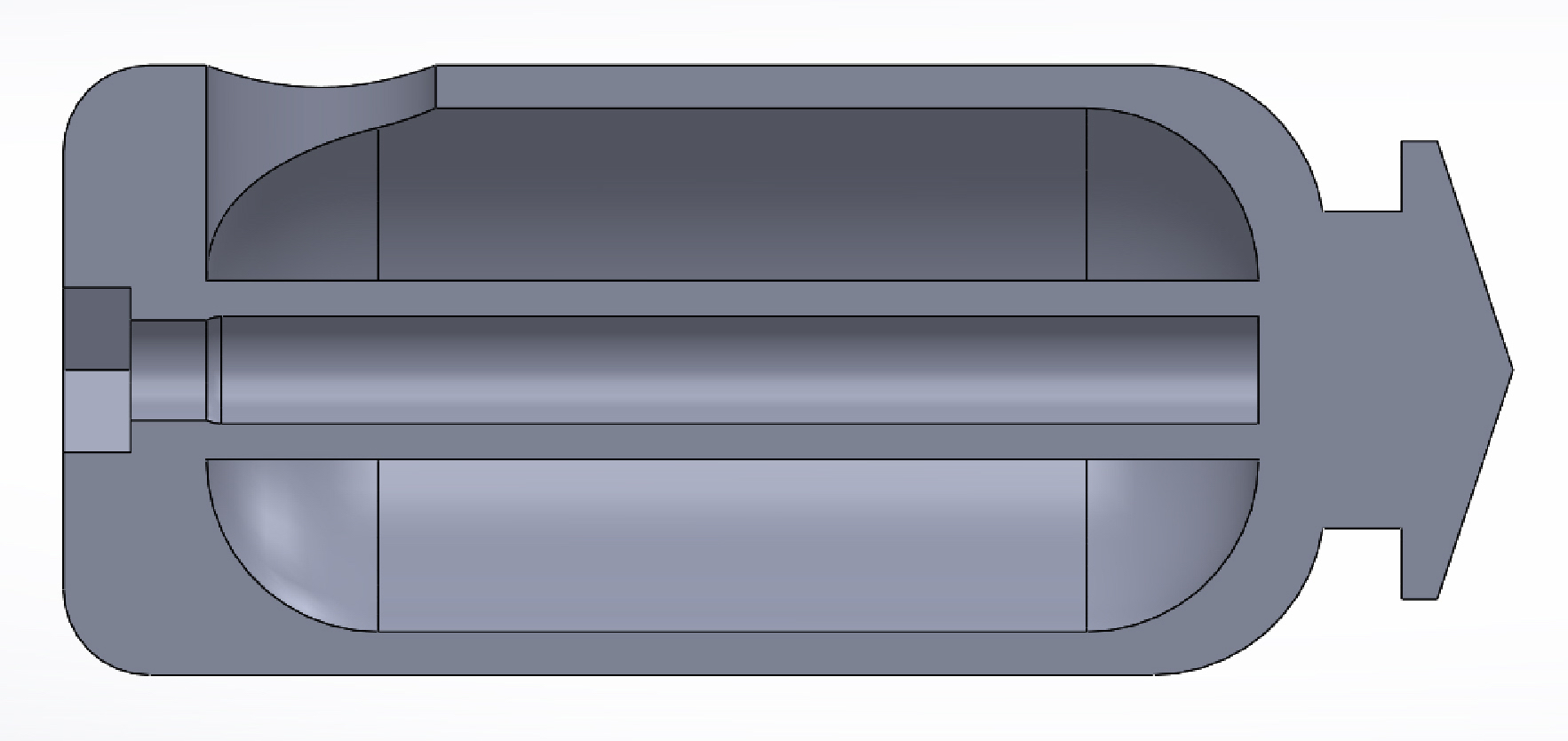
Our design uses a single captured nut to drive the piston. The piston is printed, and its base contains a recess fitted to a M3 bolt. After the bolt is seated in the recess a cap is glued to the end of the piston capturing it. The final design with the new piston can be seen in the mockup below. (The nut capturing cap is not visible so that the nut recess is).
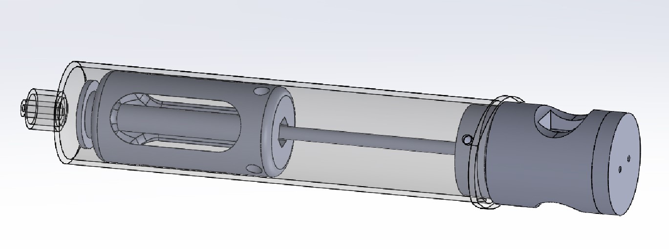
In moving to a smaller piston, our design is also testing the use of commonly available geared motor and threaded shaft modules. The motors required volume is significantly smaller than the continuous rotation RC servos used in the Glider designs. Small enough that the motor and gearbox can be completely glued inside a 3D printed housing – enabling use of brushed motors in a flooded compartment.
This design requires cutting the tops off the syringe so the entire buoyancy engine is a cylindrical diameter of the syringe shaft. The motor module is secured to the syringe by both glue – to form an air tight seal – and 1.75mm cross pins to counter shear forces caused by internal / external pressure differentials. The cross pins are dimensions so that prices of 3D printer filament can be used for the pins.
The motor housing has two cutouts that expose the motor walls for directly to the surrounding water for cooling, while the glue seal keeps the inside of the motor watertight. While this does turn the motor body into a pressure vessel – this works for the pressure differential found operating at shallower, less than 10 meter, depths we intend for this design.